Raster is faster, but vector is corrector. Part 3
Part 3 of 3.
Constructions jobs use vector models, so ag should as well?
For every complex problem there is an answer that is clear, simple, and wrong. - H. L. Mencken
It's worth examining why construction work sites are dominated by vector based data models. There are multiple contributing factors, and in totality they add up to a compelling case. History, professional requirements, and solid practical exigencies are all involved.
Construction firms were early adopters of Computer Aided Design (CAD). The earliest CAD packages were designed for engineers doing 2D drafting and 3D mechanical design. Land surveyors were also quick to adopt CAD. In all these cases the professionals involved had an existing history of creating and visualizing models on paper. Points, lines, and polygons plotted on drafting tables with protractors and T-squares. It was inevitable that in the transition to digital tools these professionals would seek familiar methods, models, and algorithms. Established practice does not preclude disruptive changes in methods, however, so there is more to the story.
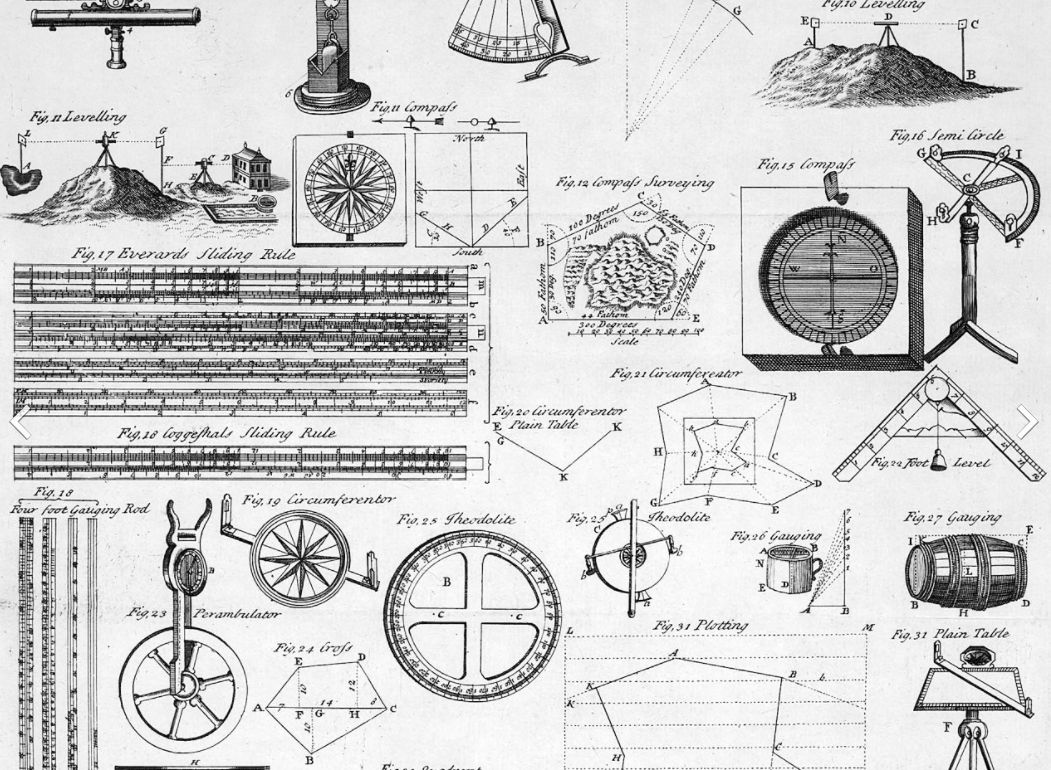
Engineers and surveyors have a long history of using "vectors"
Early models were not created with machine control in mind. Computers and CAD well predated the widespread use of precision GPS in civil construction environments. Models built by hand (mouse clicks stringing together various key points) needed to be simple to construct, and visually interpretable by site overseers. Emphasis was on conveying key concepts and important boundaries, grades, and breaks. More precise local intricacies were likely to be conveyed by annotations and notes, rather than by direct representation on plans. Compute power was limited, which also favored simple "outline" type representations. The fact that these vector representation could be extended and converted into useful 3D models for machine control when the technology became available was probably both a happy coincidence and a fortuitous development efficiency.
Another important factor is the regulatory and reporting requirements in civil projects. Historically, the submission of plans and reports to authorities was done using line drawn representations on paper. Much of this may now be digital but the format remains the same. Plans like this remain a highly effective and well understood method for recording and communicating intent and results. Using the same vector based packages for both this and the design work itself is an efficiency that continues to make good sense to civil design engineers.
Finally, and importantly, the majority of construction topography tends to be technically favorable to vector representation. As discussed earlier, vector meshes are well suited to designs that are faceted, have abrupt linear breaks, and non-uniform elevation variability. In other words, the types of designs you will most often find in construction work.
Below you will see two representations of part of a housing development project. The first (2D line drawn mesh) is from the site developer. In it you can see a road with house pads on either side. It is worth noting the variance in triangle size. The house pads have few triangles, all of them large. The road edges have many small triangles. This makes sense because the house pads represent large areas of uniform planar nature, while the road edges are small curvilinear features that change elevation abruptly over short distances.

The second (3D vertically exaggerated) representation is the same design converted to a raster surface using 25cm (10 inch) pixels. Even without any sort of statistical analysis you can see it does a good job of representing the various planes and breaks present.
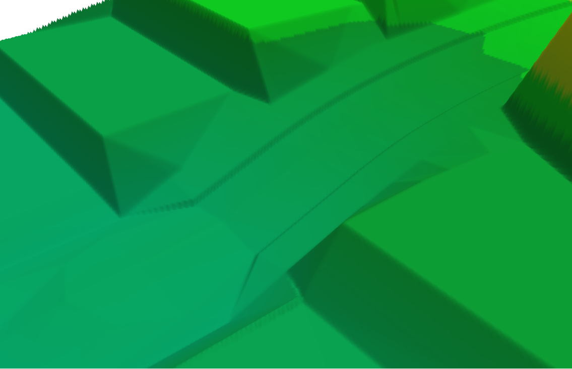
But compare the file sizes. You can't compare the raster control (.pctgdp) file at 1.5MB to the DXF (a commonly used vector format) at 2.6MB. This is because the raster file uses internal compaction and the vector format doesn't (in this case). If you compress the vector file you get a fairer comparison. At 158KB the vector file is an order of magnitude smaller than the raster file. Understanding how vectors work, this should not be unexpected. Any advantage the raster design may have in terms of computational efficiency will be rendered irrelevant, there simply aren't enough triangles in this design to cause difficulties for any modern system.

It is clear that there are valid reasons for the dominance of TINs on civil work sites. Given that, it might be curious to some that the opposite case exists in agricultural applications. In ag the vast preponderance of machine control systems use raster based terrain models.
Unfortunately for those who prefer their answers clear, simple, and wrong, there is again a multiplicity of factors in play. These relate less to history (see later), and more to the technical and practical requirements of the work.
There are aspects of agricultural earthworks that closely resemble civil earthworks. Drains, roads, shed pads, dam walls. Requirements and designs for these are not going to be massively dissimilar in ag. Albeit without a lot of the red tape, regulation, and potential liability issues.
But initially, machine control for ag wasn't about drains or roads. The fact is that you can cut a drain by eye, do a half-decent job, and mother nature and the next rainfall event will take care of a few imperfections for you. The real benefits of machine control came from full field designs. This was where the money was. Moving dirt is expensive and the costs are directly related to how much dirt you are moving. The amount of dirt moved while finessing a drain is nothing compared to what gets moved when leveling1 a full field. The ROI on getting a field put to grade quickly and efficiently is the reason most ag systems get bought.
Accordingly, ag systems will normally be optimized to perform full field leveling.1 You can create a field to be a large planar surface (which would favor a vector terrain model). However, farmers were quick to realize that they could meet their trafficability and drainage goals by being more nuanced in their rearrangement of the terrain. This saves $$ in terms of dirt moved. What's more, there is less soil disturbance, leading to better agronomic outcomes.2
The upshot of this is that designs for agricultural fields tend to have characteristics that are fundamentally different from their civil cousins. You normally don't see abrupt elevation or slope changes in designs. Tractors don't respond well to random tank traps. Often the point of leveling is to remove these 'features' (eroded washes, or melon holes). It's far more common in full field leveling to see gradual slope changes. This is good for tractors and implements, and it's often good for irrigation and drainage. However it does not play to the strengths of triangular meshes.
Consider the field terrain model shown below in 3D. This model represent 200ha (500ac) of fairly marginal melon hole (gilgai) country. The design is a full field optimization intended to drain the melon holes while moving the minimum possible amount of dirt. So little dirt is moved that you would have trouble visually picking the differences between natural and design surfaces without the benefit of a cut/fill map.
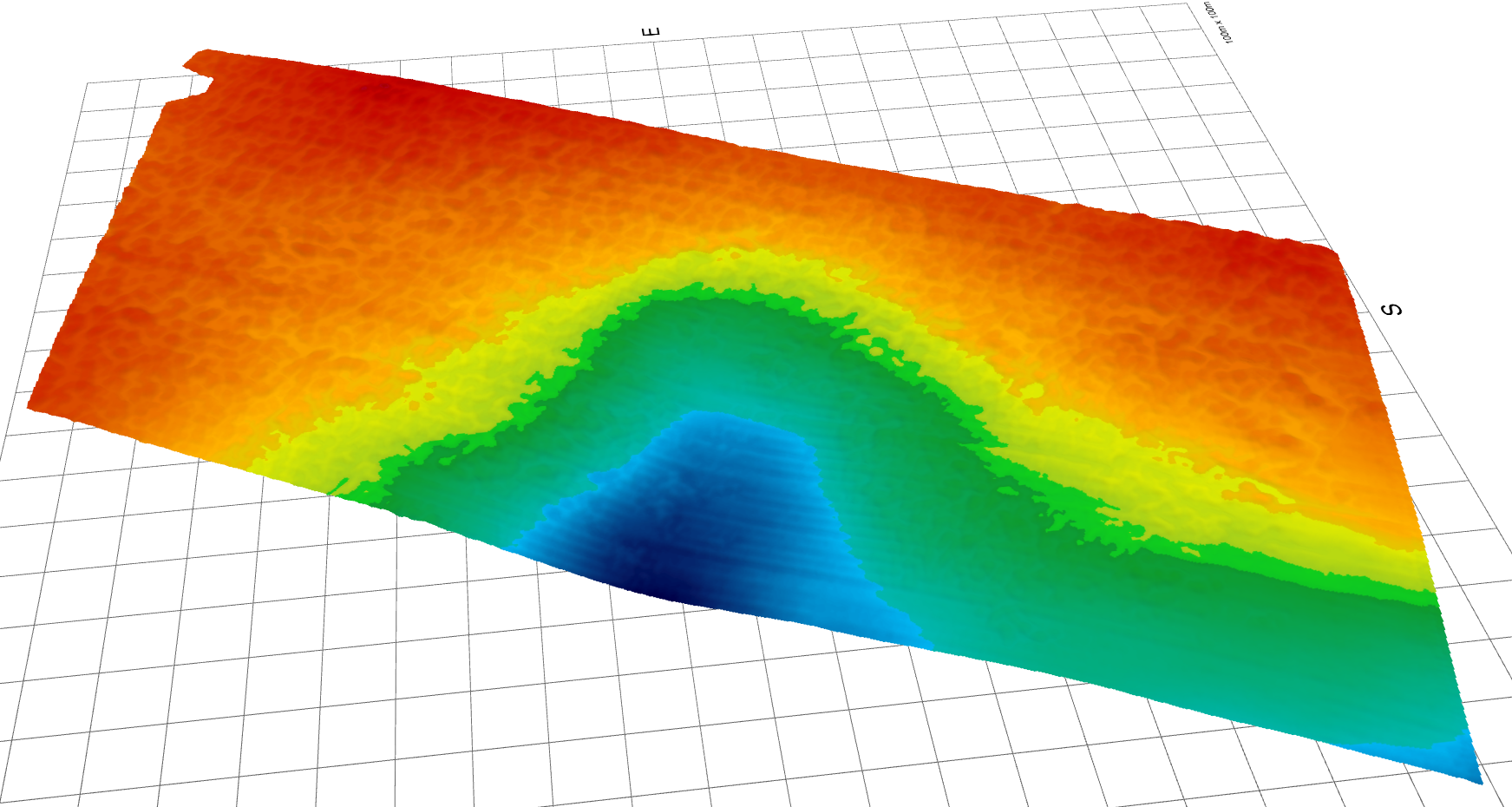
200ha (500ac) of drained melon holes. 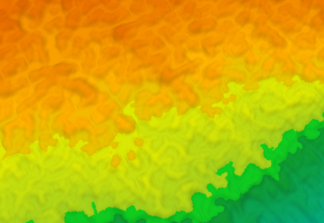
200ha (500ac) of drained melon holes. Z axis exaggerated. DETAIL VIEW.
It is worthwhile comparing this terrain to the previous (housing development) design. That terrain was characterized by large uniform planes interspersed with sharp slope changes and small angular features. This terrain is largely composed of uniformly variable short range humps and hollows. Below you see can see a small section of this design represented as a TIN (the whole field is not shown because it is not possible to see the triangle edge detail when zoomed to full extent). What is of note here is the triangles are uniformly small. The lack of any large uniform planes combined with lots of short range variability ensures this. Note the 50m (55yd) scale. In the 3D full field view the background grid lines you can see are spaced 100m (110yd) apart.
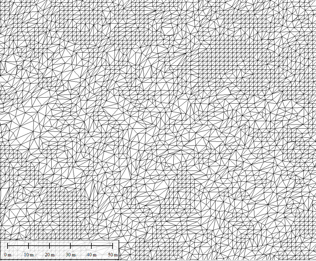
In terms of file size we see exactly the opposite of the civil design. You can compare the .dxf file and the .jsongrid file (they are both uncompressed text representations of two designs). Or you can compare the .7z and .pctgdp files, which are compressed versions of the respective vector and raster designs. In either case the gridded format is far more efficient in terms of storage. However, the real kicker is the computational cost relating to the vector model. With a fast processor, and some smart programming it can be handled, but that is not the point. In this situation the raster data model is inherently a better choice.

There is certainly still a demand for completely planar fields, perhaps with the odd break line. However, even in these situations, triangle meshes are still usually at a disadvantage. The reason relates to the pre-existing natural surface, and to economics.
On a per acre basis less can usually be spent in an agricultural application than a civil one. This has multiple implications. It may mean that the design has to be done by the operator without help from a surveyor or engineer. It may mean that physical markers and layout work are impractical. It will certainly mean that you can't afford to have engineers wandering around the site telling you where the next load of fill needs to come from. This is the reason that cut/fill maps are so important in agricultural applications. The operator benefits from understanding where dirt is coming from, and going to. The cut/fill map is a combination of the design and the pre-existing natural surface. Regardless of how flat your design is, you're still likely to have a natural surface that is more efficiently modelled by a raster.
I did mention there was some history involved with the choice of rasters in ag. Prior to GPS it was often most convenient/practical to "grid off" a field and take spot heights. Pegs might be put out. After all the manual calculations were done scraper operators were given gridded cut/fill maps as a guide for understanding where to cut and fill. Some still like having these maps today. I'd tend to put this more in the "curious coincidence" basket rather than the "cause and effect" basket. 😁 The history that matters more, is the lack of history. With no established methodology for the digital design of field terrain the pioneers in this space were not shackled by existing paradigms and tools. They simply picked what made the most sense at the time.
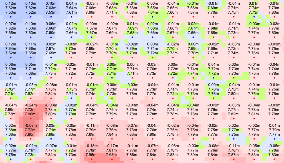
Operator cut/fill map 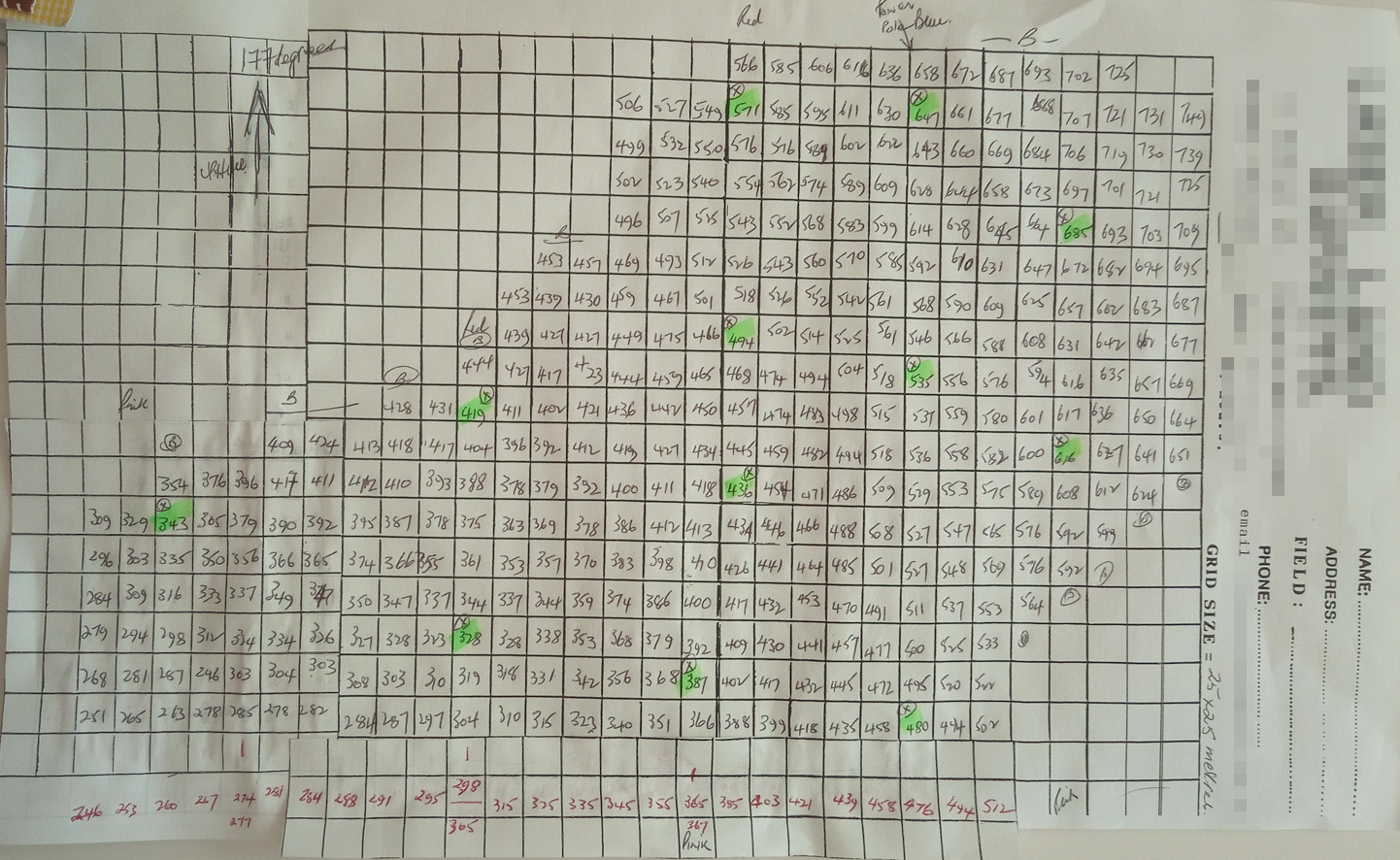
Old school survey
Hopefully you can see that there are boringly rational reasons that ag and civil design files have historically taken a different path in terms of their core data structures. There is nothing more frustrating than hearing someone say "They do X in construction, so it must be better". The expressed sentiment is both naïve and cringeworthy. It is an obsequious devaluation of the truly complex designs that agricultural earthmovers implement, and of the capability and professionalism of the support chain that stands behind them.
The Ag/Civil crossover market
Many agricultural operators (contractors in particular) find a use for their machines on civil jobs from time to time. Is this a reason to have a control system that uses a vector based terrain model? If you have read this far you will realize that I don't inhabit a world with black and white answers. The answer? No. Yes. Maybe. It depends.
I can say that the answer isn't going to depend on the relative capabilities of either raster or vector data structures. Both will work fine for the majority of civil jobs you are likely to encounter. When using a raster model you will need to use a smaller pixel size, perhaps 25cm (10") or 50cm (20"), and this will lead to larger control file sizes. But given the relatively small areas most civil jobs cover, this is unlikely to be an issue.
What is important is making sure you are able to import the design file from the engineer or designer providing it for the job (as you are unlikely to have to create the design yourself when performing civil work). This is a function of the software, not the data model. Converting between raster models and vector models is a whole other post, but most modern agricultural packages should be able to do this without issue.
Ask the supplier of your machine control system if they have a document explaining how to import civil design formats. If they are worth their salt, they will. It will be called something like, I don't know, "Guidelines for importing Civil Designs.pdf". Yeah, ask for that.

In my experience one thing that is very helpful on most civil jobs to is the ability to use the design engineer's linework in your control system. These lines can sometimes be used as auto-steer guidance curves, but are always helpful for keeping your blade edge aligned with whatever linear design features are present.
The future
It's tempting to think that advancing computer power will make raster/vector choices largely irrelevant in the future. Faster clock cycles can compensate for the inefficiencies of both vector and raster model at certain times. If history is a guide, however, all that a faster computer means is that we will want to use more data and more precise data models. We will quickly bog them down again.
One can expect creators of agricultural design packages to increasingly cater to the needs of civil earthmovers. To expect the opposite (makers of civil packages to create packages for agriculture) is probably a bit hopeful.
In my view the future lies with hybrid models. There are definite complexity increases and computational trade-offs when doing this. But the benefits of capitalizing on the best data model for a given topographic reality, or algorithmic requirement, are compelling. This has already started to happen in at least one of the agricultural packages, and adoption will no doubt broaden.
In summary
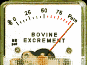
Playing favorites between one data structure or another is a game for marketing executives. If you are talking to a sales rep and they say "my software is better because it uses triangles rather than grids" (or vice versa) then your bullshit-o-meter ought to nudging the redline.
It would be nice if you could delve into just how well their data model (whatever it is) has been implemented, as this will be the thing that matters. But this is a tough ask. The most practical thing you can do here is to look at the range of applications the software is already working in.
If it all seems too technical and too hard, don't stress. You can get too worked up about data formats and design imperfections. Ultimately it is the practical result that is important. Many technical sins will be smoothed over by a good operator and 16ft scraper blade.
Post series:
- Introduction & data models
- Comparing terrain representations
- Civil vs Agriculture
Acknowledgements to Jay and Jonathan for their helpful feedback on the series draft.
The term "Leveling" is not used in this context to refer to actually making something "flat" or "dead level". It is a colloquial earth moving term deriving from older laser leveling activities (where the aim normally was to make thing pretty level) and refers more generically to any full field agricultural earthworks or land forming activities. Paradoxically, it can actually mean making a field less level, by adding more slope to part or all of it.↩↩
Construction engineers and agronomists see dirt in different ways. For an engineer the physical qualities (how it compacts, moves, and bears loads) are usually paramount. For an agronomist both physical and chemical properties are important. The fertility characteristics of soil are usually stratified with depth. Exposing underlying subsurface layers can cause productivity losses, as can burying fertile surface horizons that are rich in organic matter and nutrients. The mechanical destruction of pores and structure can have deleterious effects on soil water holding capacity. Land forming should always be performed with an eye to minimizing disturbance, and/or replaces layers in a way that protects soil productivity.↩