Raster is faster, but vector is corrector. Part 2
Part 2 of 3.
In Part 1 we looked the different types of data structures used in machine control systems:
- Algorithmic.
- Vector (triangle mesh).
- Raster (grid).
- Hybrid.
Here in Part 2 we take a look at the strengths and weaknesses of these different models.
Pros and cons
Each system has strengths and weaknesses.
Algorithmic terrain models are (generally) highly computationally efficient and robust. They can be implemented on low-end electronic hardware. Normally they are found in systems which only create simple planes. If more complex design surfaces are required (with random undulations and arbitrary grade breaks) it quickly becomes difficult to formulate an equation which accurately models the design. The nature of their usual use-case (unsophisticated plane work) means that few parameters are required and a very simple user interface can be implemented. From a storage standpoint algorithms can basically be considered to have a zero footprint. The disk and memory usage is negligible.
Raster and vector data models are most commonly used in modern machine control. Vector models tend to be more ubiquitous in civil construction systems and raster models tend to be more common in agricultural systems. We will get to a discussion of the reasons for that.
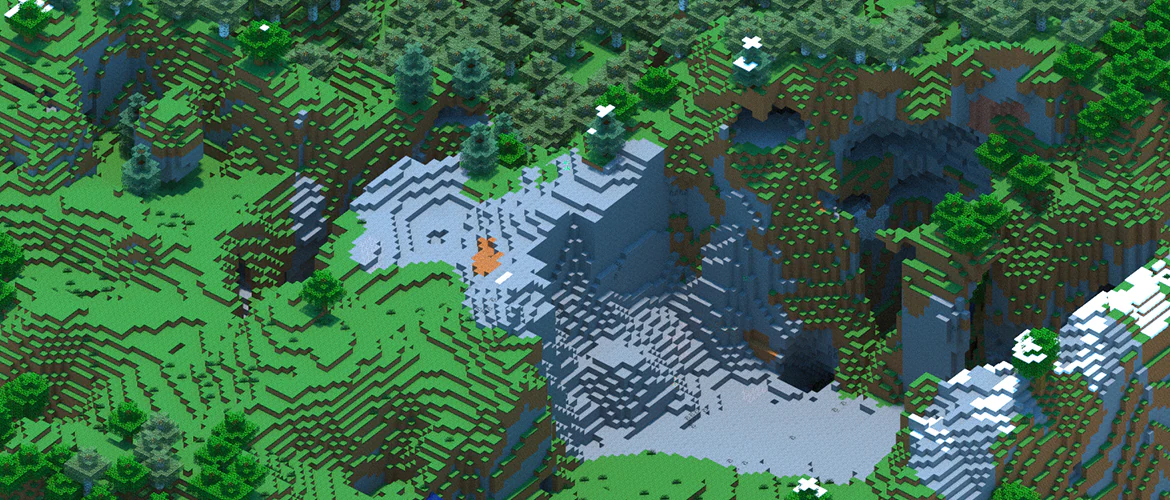
Minecraft terrain can be thought of as a rudimentary "raster surface".
There are various ways of at looking at the differences between raster and vector surface representations.
If the point density of both the raster and vector data structure are similar the raster surface will consume less memory and disk space for the same design. This is because locations for each point in the raster grid are not individually stored.
A computer does less work when querying a raster surface (relative to a vector surface) for heights. This is important because machine control systems do this many times every second. A raster data structure is essentially a "lookup table". By knowing the offset of the query location from the raster's origin it is trivial to calculate the row and column of the target pixel. This defines the position of the target elevation in the stored list of elevations. Computers are exceptionally fast at retrieving values from known locations in lists. Modern systems will look up more than just the target pixel, they will normally query the target pixel's neighbors to create (interpolate) a more accurate target value. The speed at which this occurs makes the cost of this negligible compared to what is described in the next paragraph.
To find an elevation in a TIN the computer must first find the triangle that contains the target location, and then it must use the three corners of the containing triangle to calculate the exact height of the target location. Doing the within-triangle calculation is not expensive, but finding the correct triangle is. The difference in lookup times become greater as the detail of the map increases. This heavy computational requirement disadvantages vector mesh representations of highly detailed maps. Code jockeys use clever shortcuts to make sure that this lookup process does not overwhelm the computer, but poor implementations will struggle.
Another difference between the two data structures is the ease with which surface manipulation occurs. This is important because it impacts the types of surface designs that can be created, or the costs at which they can be created.
Raster grids are generally cheap to work with (in a mathematical sense). They are simply large data tables. Comparing two grids (such as you might do when subtracting a design surface from a natural elevation surface to create a cut/fill map) is as simple as iterating over all rows and columns and comparing the matching cell in each grid.
Vector surfaces have a problem here. Because the triangles in the natural elevation surface may not be the same as the ones in the design surface (and they shouldn't be if both structures have been created to optimize mesh performance on their respective terrain surfaces) you can not directly compare triangle to matching triangle. This gives rise to a situation where you need create a whole new set of triangles based on intersections of triangles in the two existing meshes. It is computationally a more difficult task. (One way of dealing with this is to forgo the vector layer and instead create a raster cut/fill map by systematically sampling the two vector surfaces in a grid pattern).
Even within the same layer things tend to be simpler with raster data sets. Smoothing a field surface is a very common use case for machine control in agriculture. With a raster data structure you are simply iterating over each pixel and averaging the current pixel value with neighboring pixel values. It is trivial to implement and very fast to perform. With a triangle mesh it is more complicated. Not only are the neighborhood averaging calculations more expensive, you must also subdivide and rearrange triangles in order to match the new surface curvatures of the smoothed map.
Knowing the above you may wonder why you would ever use a vector based DEM. The above comparisons are intentionally unfair (to illustrate differences) in that they hinge on both data structures having roughly the same number of points. It also assumes that the work area is roughly rectangular. If either of these are not the case, then the landscape changes (pun intended).
The effect of field shape.
Raster data layout (normally) requires a set number of rows and columns. This means that the coverage area is always rectangular. While many agricultural fields are roughly rectangular, there is a significant proportion that are not (or that have non-field inclusions ("holes")). Raster structures handle "out of bounds" areas by not putting an elevation at the corresponding grid locations. However, something must be put at the location, because the table of rows and columns must be maintained for elevations to be located correctly. It is important to note that entering an empty value (as a placeholder) takes just as much memory as entering an actual elevation.
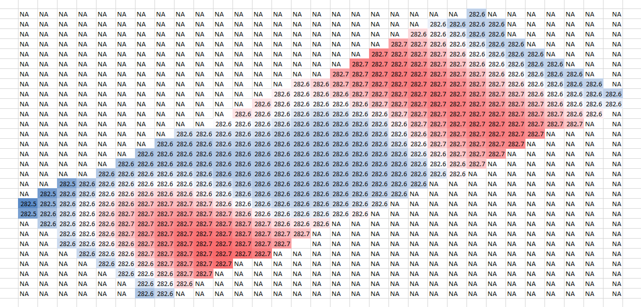
"Empty" cells must be maintained to keep the rectangular structure.
A rotated grid might be a solution in this example, but this is not always effective.
This means that non-rectangular field shapes can cause raster formats to waste a lot of space. There are mathematical techniques to mitigate this effect, but these come at a computational cost.
TINs do not have the same limitation. Triangle node points do not need to be distributed on a regular grid. Thus they can hug boundaries fairly exactly.1 So a TIN will not "waste" disk or memory space on non-field areas.
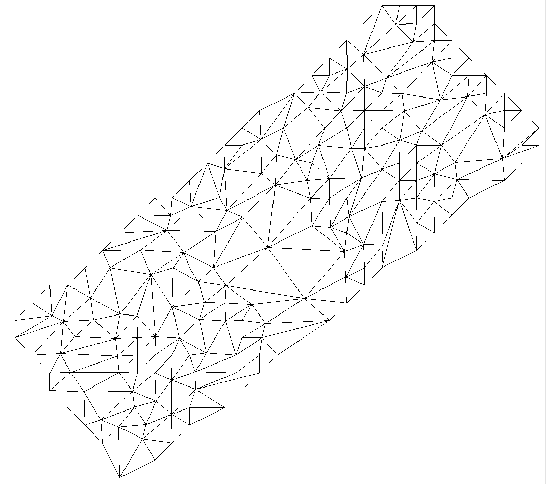
The vector representation of the same terrain as above does not need to extend beyond the boundaries of the work area.
TINs show a particular advantage in this regard when the design is solely made up of long curvilinear features with large empty areas in between. Civil road construction designs are examples of this.
The effect of resolution.
Regular raster implementations are, well, regular. They have a uniform resolution (spacing, or "point density"). Grid points can be laid out at 50cm (1.6ft), 1m (3.3ft), or 5m (5.5yd), or whatever. But it is constant. The resolution that is appropriate for any given design can be determined by (in theory at least) the Nyquist sampling theorem.
What this means in a practical sense is that to better characterize small changes in landscape (short range bumps and dips) grid spacing must be decreased. Because location is a 2 dimensional concept, an increase in resolution will be accompanied by a geometrical increase in data points. If the grid cell size is halved, there will be a quadrupling in the number of data points. While this is easier to visualize in a raster layout, the same basic premise applies to TINs. The amount of data to store and process increases at roughly the square of the increase in resolution.
Where vectors have an edge is that there is no requirement for all triangles to change size uniformly. If only part of the design requires a higher resolution, then that section of the design can change, leaving the remainder untouched. Significant size reductions are possible, with resultant storage and computational benefits. Raster models (usually) can not do this.
The effect of landform.
The three dimensional shape of a field design has large implications for the relative performance of the different data model types. Planar designs (made of a simple single- or dual-plane slope) provide no challenge for any of the discussed data models. The design model will be trivial in all cases and model performance basically identical.
As soon as we get beyond simple "laser" layouts differences begin to open up in the performance of different data models. We can largely forget about algorithmic models at this point due to the difficulty in formulating them for anything but the simplest of designs (a shame, because they are elegant and efficient).
Unequivocally, both raster and vector data structures can represent any given surface with equal accuracy.
Unequivocally, both raster and vector data structures can represent any given surface with equal accuracy. However, due to their differing spatial structure requirements the two approaches can require a vastly different amount of data in order to achieve an equivalent accuracy.
Vector designs tend to be advantageous where elevation variability differs greatly in different areas of the design surface. They also shine when field surfaces are "faceted". That is, where the field design is made up of planar sections that abruptly transition from one to the next. An example of a design that might be particularly well suited to a vector triangle mesh would be one where the design was composed of a single-plane field bordered by an abrupt linear drain. In this case a simple, sparse TIN could be created to nicely match the field, the drain, and the interface between them. A raster layout would be far less efficient due to the high resolution needed to accurately characterize the drain. This high resolution grid would be present for the entire field surface. The resultant raster file would likely be far larger than the TIN.
Raster based structures tend to be advantageous where there are continuous and gradual slope changes present over the entire design work area. In this situation a TIN needs to have just as many triangle nodes as the raster grid requires grid cells in order to accurately represent the design. However the greater computational efficiency coupled with the smaller per point data size makes the raster model a better choice. Examples of such designs include most modern (dirt optimized) variable grade irrigation fields, melon hole (gilgai) drainage projects, and multi-directional crowned fields
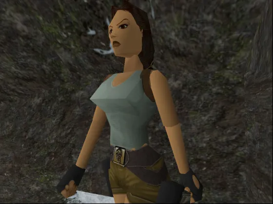
An early version of the video game "Tomb Raider" nicely illustrates the challenges of modeling curves with a triangle mesh.
So what is important?
There are many features to consider when evaluating a data structure's fitness for a particular purpose. How easy is the design file to make? How big are the design files when stored on disk? How accurately does it model the surface? How suited is it to the types of in-field manipulations that are likely to be required? How computationally efficient is it for a computer to use and display? Can it be easily converted to other formats?
There likely is no universal "best" method or structure for creating digital elevation models. There will always be compromises and tradeoffs. It is also worth mentioning that new methods are constantly being invented in order to improve performance and accuracy.
A critical factor is how the actual models and algorithms are programmed. Implementation details in code are massively important. For instance, do you store heights, or do you store height differences? Do you use compression to decrease file sizes, or do you optimize on-disk structure to maximize random location read times? Do you brute-force data lookups, or do you employ spatial search algorithms? Do you optimize for "read only" field scenarios, or are you expecting the data to be altered on-the-fly in the field? There are hundreds of impactful choices to be made when writing the code to create and interact with a data model.
Although a raster representation may be theoretically better suited to a given application, it can be outperformed by a TIN if the raster is implemented poorly and the TIN is implemented well. And vice versa. One of the vector based agricultural file format implementations the author is aware of uses a single shared set of triangle nodes for both design elevations and natural surface elevations. This curious choice simplifies computational requirements but greatly limits the format's ability optimize for both surfaces. This has follow-on implications for the cut/fill map. Good choice or bad choice? 🤷 The answer (of course) is "it depends...". 🙄
It is worth knowing the following software developer insight. Programs are built for a purpose. They tend to exist within a certain set of boundaries. If you get outside of the scenarios the developer had in mind when he/she wrote the software, things can fall apart.
Farmer A: Developer, I really need this feature in the software.

Developer: Ok. Send me your elevation survey and I will build something for you.
.
.
Developer: Here you go.

Farmer A: Thanks, works a treat.

Developer: Nice. I'll tell everyone else about this new feature.
.
.
Farmer B: Well, that doesn't work at all.

Developer: Bugger. 😢
Just because something works well in one set of circumstances doesn't mean it will in another. The 'changed circumstance' can be as simple as field size. The methods and algorithms that work well in a 10ha (25ac) field may collapse completely in in a 100ha (250ac) field. Developers are like everyone else, they deal with what is in front of them. They normally won't try to optimize for eventualities they don't expect to happen, or that they don't know exist. The insight here is that scale and market adoption count. The more farmers using a software package, the more scenarios the developers will have encountered and accommodated. This leads to better robustness and flexibility.
How can you tell if your data model is performing well?
Most operators will only become aware of data model problems when their software either outright refuses to load a prescription map, or if loading the map causes the controller to lag appreciably. The sources of this behavior can be varied, but excessive file size is the normal cause. Too big an area, too many triangles, or too small a grid spacing. In farming scenarios this is more likely to be a vector format issue, but not exclusively.
If the map does load and the machine operates you're not out of the woods. The issue now is whether or not the design performs as expected. Raster maps with insufficient resolution, for instance, will often struggle to maintain a smooth grade along drain batters (particularly if the grid alignment does not match the drain alignment).
Adjusting map resolution can improve or decrease performance. Too much resolution and computational issues begin to occur. Too little and the field design surface becomes poorly represented. It can be possible to judge by eye if a model is under-representing the surface of interest. If you can clearly see the the outline of the model's basic geometric structure in the resultant map, this is a possible indicator of insufficient model resolution.
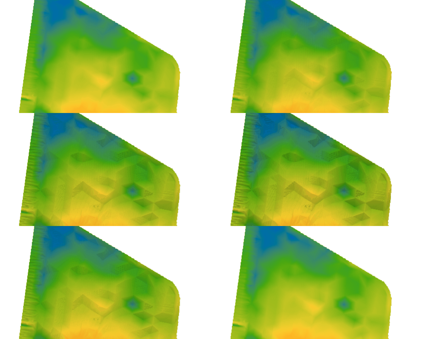
A surface model where the triangle mesh is clearly evident. While not definitive, this can be indicative of insufficient model resolution.
Next up: Part 3. Understanding the differences in Civil and Agricultural applications
Post series:
- Introduction & data models
- Comparing terrain representations
- Civil vs Agriculture
Note that it is generally not true to say that a TIN can match a field boundary exactly. Triangle edges must be straight so by definition it is impossible for a TIN to exactly match a curved boundary of any sort. While two vertexes of a triangle can be put exactly on a field boundary, the edge will only match exactly if the boundary is also straight between those two points.↩